Mapping Complex Distributed Systems with C4 Diagrams and Structurizr DSL
As distributed systems grow in complexity, architects face an increasingly challenging task: how do you effectively communicate the structure and relationships within a system that spans dozens of services, multiple teams, and various technology stacks?
Traditional architectural diagrams, especially those based on UML (Unified Modeling Language), were once the industry standard, but have largely fallen out of favour for documenting modern software systems. UML’s comprehensive notation often leads to overly detailed, hard-to-maintain diagrams that struggle to keep pace with the rapid evolution of distributed architectures. As a result, many teams find that classic boxes-and-arrows drawings, whether UML or ad hoc, quickly become unwieldy and confusing rather than clarifying.
Enter the C4 model and Structurizr, a powerful combination that provides a structured, scalable approach to documenting distributed systems architecture.
Understanding the C4 Model
The C4 model, created by software architect Simon Brown, provides a hierarchical approach to documenting software architecture through four levels of abstraction.
The different levels of zoom allow you to tell different stories to different audiences. You don’t need to use all four levels of diagram; only those that add value. The system context (level 1) and container diagrams (level 2) are sufficient for most software development teams.
Context (Level 1)
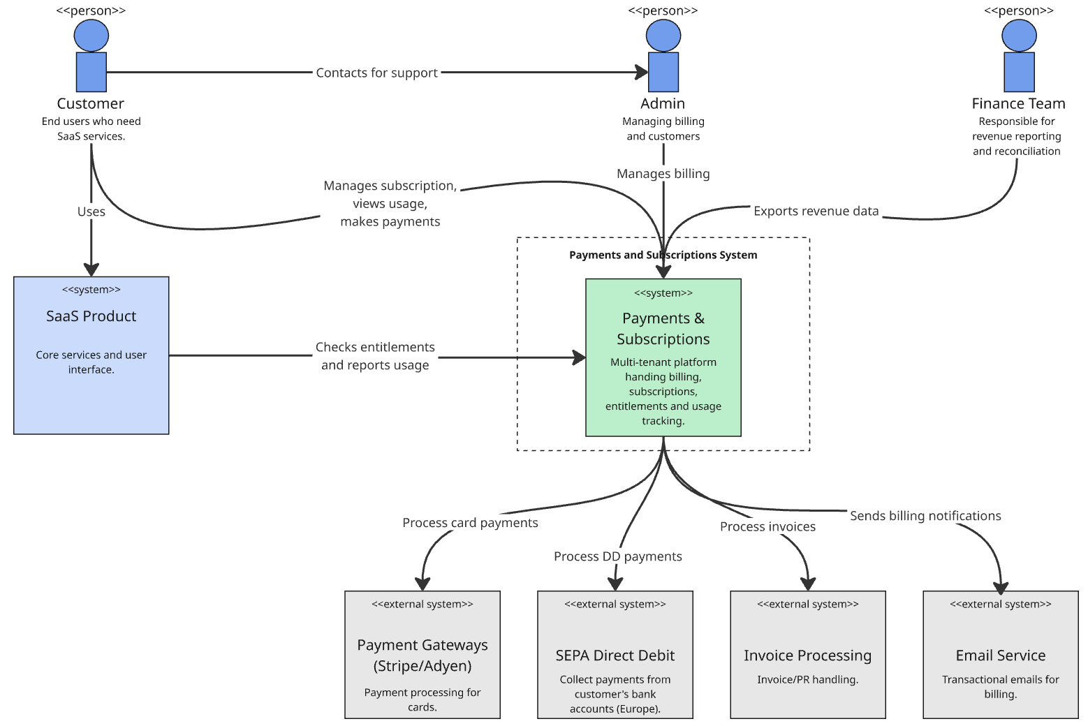
The system context diagram shows how your software system fits into the world around it. A software system is typically something that a single team are responsible for producing. This high-level view focuses on users, external systems, and the primary purposes of your system. Think of it as a map showing your system as a single box surrounded by its users and neighboring systems.
Here is an example system context diagram for a Payments & Subscriptions Platform. At the highest level, the Payments & Subscriptions Platform sits between users, front-end applications, and external services like payment gateways and tax providers.
Containers (Level 2)
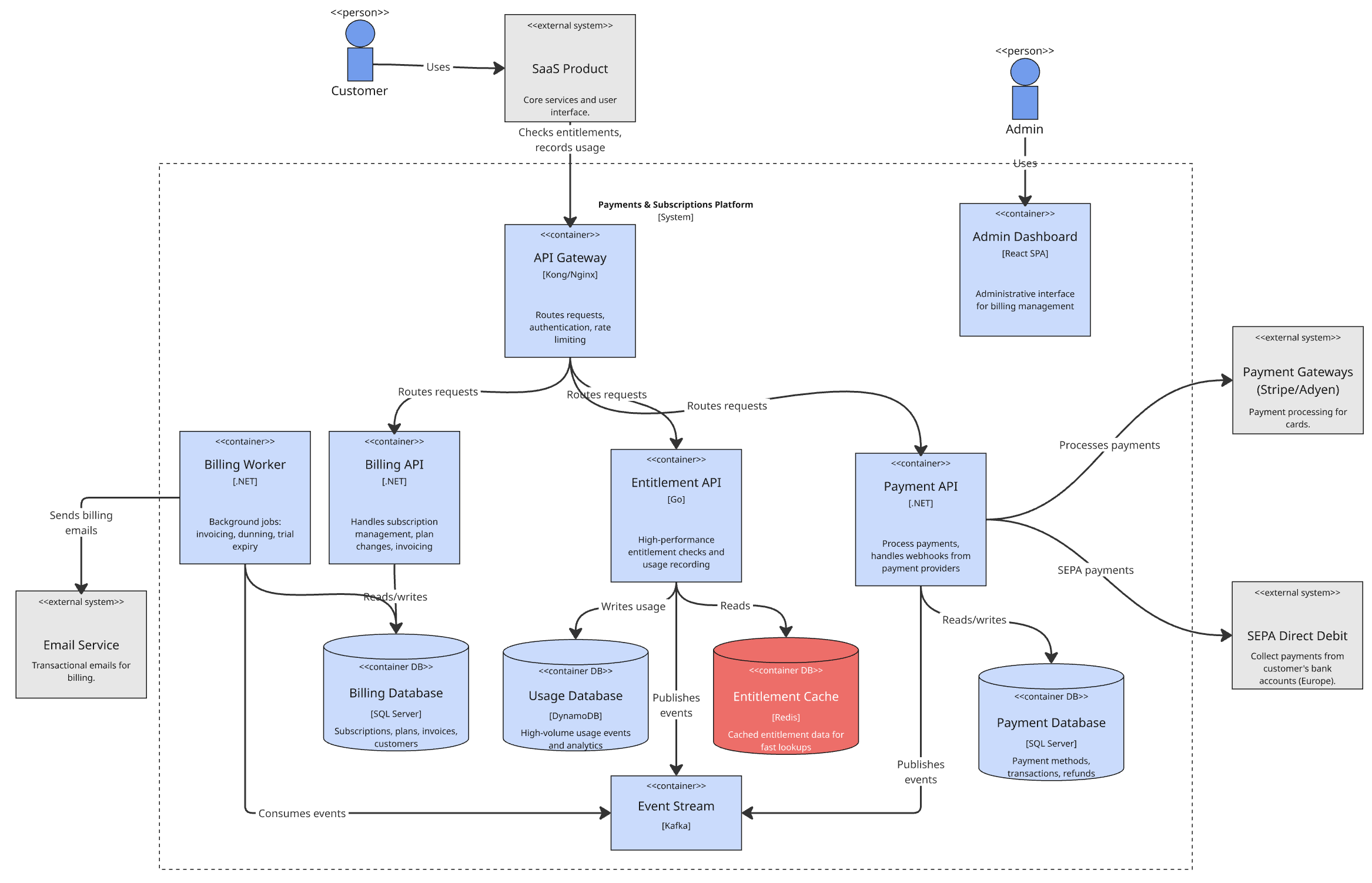
Container diagrams breaks down your system into major technical building blocks. In distributed systems, these are typically your microservices, databases, message queues, API gateways and web applications. Each container represents a separately deployable unit that executes code or stores data.
Zooming in on our Payments & Subscriptions Platform, we can see the individual containers that make up the system. This includes a set of services, data stores and infrastructure containers.
Components (Level 3)
The component diagram zooms into individual containers to show their internal structure. This level reveals the major structural building blocks within each service; the controllers, services, repositories, and other architectural patterns you’ve implemented.
Code (Level 4)
The code-level diagram provides the most detailed view, showing how components are implemented in code. While useful for complex algorithms or critical components, this level is often omitted for distributed systems documentation as it becomes too granular.
Why the C4 Model Works for Distributed Systems
The hierarchical nature of C4 diagrams makes them particularly well suited for distributed architectures. You can start with a system context diagram that shows your entire platform as a single entity, then progressively drill down into containers (your microservices), and finally into the internal structure of specific services when needed.
This approach solves several common problems with distributed system documentation. It eliminates the temptation to create massive, incomprehensible diagrams that try to show everything at once. Instead, it provides multiple views at appropriate levels of detail for different audiences; executives see the context, teams see the containers, and developers see the components.
Introducing Structurizr DSL
While many tools can create C4 diagrams, Structurizr DSL (Domain Specific Language) stands out for its code-like approach to defining architecture. Instead of dragging and dropping boxes in a visual editor, you write textual descriptions of your system’s structure.
Here’s why this matters for distributed systems. As your architecture evolves (and distributed systems evolve constantly), maintaining visual diagrams becomes a significant overhead. Teams often abandon architectural documentation because keeping visual diagrams in sync with reality requires too much manual effort. Structurizr DSL addresses this by treating your architecture as code, enabling version control, automated generation, and integration with your development workflow.
Getting Started with Structurizr DSL
Let’s walk through creating documentation for a typical distributed e-commerce system. We’ll start with a basic workspace definition and build up our architecture model with a context diagram. We’ll then move on to the container diagram.
Workspace
A workspace is a wrapper for a software architecture model, views and other documentation.
The tool that we will use for rendering, Structurizr Lite, expects a file called workspace.dsl, so let’s create that file in our architecture repository and add the code for the workspace (format: workspace "{workspace_name}" "{workspace_description}"):
workspace "E-commerce Platform" "Architecture for our distributed e-commerce system" {
}
Model
Inside our workspace we add the model. The model includes definitions using types:
- softwareSystem: the e-commerce platform that we are modelling, and other external systems that it interacts with. Format:
{system_id} = softwareSystem "{system_name}" "{system_description}" - person: the people who interact with the software system. Format:
{person_id} = person "{person_name}" "{person_description}" - ->: relationships between different software systems and persons. Format:
{from_id} -> {to_id} "{relationship_description}"
workspace "E-commerce Platform" "Architecture for our distributed e-commerce system" {
    model {
        # Define people and external systems
        customer = person "Customer" "A customer of our e-commerce platform"
        admin = person "Administrator" "Administrative user managing the platform"

        paymentProvider = softwareSystem "Payment Provider" "External payment processing"
        emailService = softwareSystem "Email Service" "External email delivery service"

        # Define our main system
        ecommerceSystem = softwareSystem "E-commerce Platform" "Core e-commerce functionality"

        # Define relationships at the system level
        customer -> ecommerceSystem "Uses"
        admin -> ecommerceSystem "Administers"
        ecommerceSystem -> paymentProvider "Processes payments via"
        ecommerceSystem -> emailService "Sends emails via"
    }
}
View
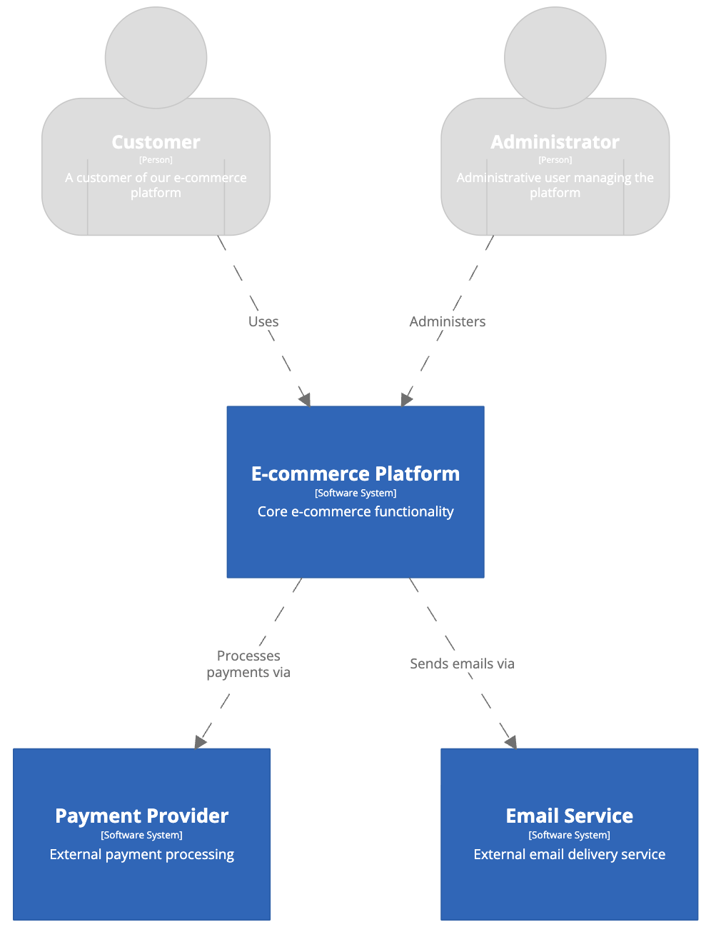
The view DSL element is where we define the diagrams that we would like to build for our model. In this example we are creating a system context diagram for the e-commerce system (systemContext ecommerceSystem "SystemContext") and including everything else from the model that has a relationship to it (include *). The autoLayout option instructs the rendering tool to generate a readable layout automatically. The styles element allows for control of the appearance of the model elements on the rendered diagram (background, color, fontSize, shape).
workspace "E-commerce Platform" "Architecture for our distributed e-commerce system" {
    model {
        # Define people and external systems
        customer = person "Customer" "A customer of our e-commerce platform"
        admin = person "Administrator" "Administrative user managing the platform"

        paymentProvider = softwareSystem "Payment Provider" "External payment processing"
        emailService = softwareSystem "Email Service" "External email delivery service"

        # Define our main system
        ecommerceSystem = softwareSystem "E-commerce Platform" "Core e-commerce functionality"

        # Define relationships at the system level
        customer -> ecommerceSystem "Uses"
        admin -> ecommerceSystem "Administers"
        ecommerceSystem -> paymentProvider "Processes payments via"
        ecommerceSystem -> emailService "Sends emails via"
    }

    views {
        systemContext ecommerceSystem "SystemContext" {
            include *
            autoLayout
        }

        styles {
            element "Person" {
                color #ffffff
                fontSize 22
                shape Person
            }
            element "Software System" {
                background #1168bd
                color #ffffff
            }
        }
    }
}
The include and exclude keywords within the view element can be used to filter which items appear within the view.
* -> *: all relationships between all elements
source -> *: all relationships from source to any element
* -> destination: all relationships from any element to destination
source -> destination: all relationships from source to destination
Viewing the diagram with Structurizr Lite
Now that we have a basic system context diagram, we can render and view the diagram using Structurizr Lite, a free version of Structurizr, packaged as a Docker container, and designed for developers who want to quickly author and/or view software architecture diagrams, documentation, and architecture decision records (ADRs).
If you don’t have docker/podman installed, I would suggest installing podman with Homebrew:
brew install podman
Then run a container with the structurizr/lite image, exposing port 8080 to the host and mapping the directory containing your workspace.dsl file to the container’s /usr/local/structurizr directory.
podman run -it --rm -p 8080:8080 -v /Users/glen.thomas/Documents/ecomm_platform:/usr/local/structurizr structurizr/lite
Load the Structurizr light web page in your browser (http://localhost:8080) and see the diagram rendered in the UI with automatic layout.
Container level diagram
Now we can expand our architecture diagrams with a container diagram for the e-commerce system. Within the softwareSystem element we will add definitions for the containers and within the model element we will map the relationships between the containers. The format for each container definition is: {container_id} = container "{container_name}" "{container_description}" "{technology}"
workspace "E-commerce Platform" "Architecture for our distributed e-commerce system" {

    model {
        # Define people and external systems
        customer = person "Customer" "A customer of our e-commerce platform"
        admin = person "Administrator" "Administrative user managing the platform"

        paymentProvider = softwareSystem "Payment Provider" "External payment processing"
        emailService = softwareSystem "Email Service" "External email delivery service"

        # Define our main system
        ecommerceSystem = softwareSystem "E-commerce Platform" "Core e-commerce functionality" {

            # Container level - our microservices
            webApp = container "Web Application" "Customer-facing web interface" "React/JavaScript"
            adminPanel = container "Admin Panel" "Administrative interface" "React/JavaScript"
            apiGateway = container "API Gateway" "Entry point for all API requests" "Spring Cloud Gateway"

            userService = container "User Service" "Manages customer accounts and authentication" "Spring Boot/Java"
            catalogService = container "Catalog Service" "Manages product catalog" "Node.js/Express"
            orderService = container "Order Service" "Handles order processing" "Spring Boot/Java"
            paymentService = container "Payment Service" "Processes payments" "Python/FastAPI"

            userDatabase = container "User Database" "Stores user account information" "PostgreSQL"
            catalogDatabase = container "Catalog Database" "Stores product information" "MongoDB"
            orderDatabase = container "Order Database" "Stores order data" "PostgreSQL"

            messageQueue = container "Message Queue" "Handles asynchronous communication" "Apache Kafka"
        }

        # Define relationships at the system level
        customer -> ecommerceSystem "Uses"
        admin -> ecommerceSystem "Administers"
        ecommerceSystem -> paymentProvider "Processes payments via"
        ecommerceSystem -> emailService "Sends emails via"

        # Define relationships at the container level
        customer -> webApp "Uses"
        admin -> adminPanel "Uses"

        webApp -> apiGateway "Makes API calls to"
        adminPanel -> apiGateway "Makes API calls to"

        apiGateway -> userService "Routes requests to"
        apiGateway -> catalogService "Routes requests to"
        apiGateway -> orderService "Routes requests to"

        userService -> userDatabase "Reads from and writes to"
        catalogService -> catalogDatabase "Reads from and writes to"
        orderService -> orderDatabase "Reads from and writes to"
        orderService -> paymentService "Initiates payments via"

        paymentService -> paymentProvider "Processes payments via"
        paymentService -> messageQueue "Publishes events to"
        orderService -> messageQueue "Publishes events to"
        userService -> messageQueue "Publishes events to"

        orderService -> emailService "Sends order confirmations via"
    }

    views {
        systemContext ecommerceSystem "SystemContext" {
            include *
            autoLayout
        }

        container ecommerceSystem "Containers" {
            include *
            autoLayout
        }

        styles {
            element "Person" {
                color #ffffff
                fontSize 22
                shape Person
            }
            element "Software System" {
                background #1168bd
                color #ffffff
            }
            element "Container" {
                background #438dd5
                color #ffffff
            }
        }
    }
}
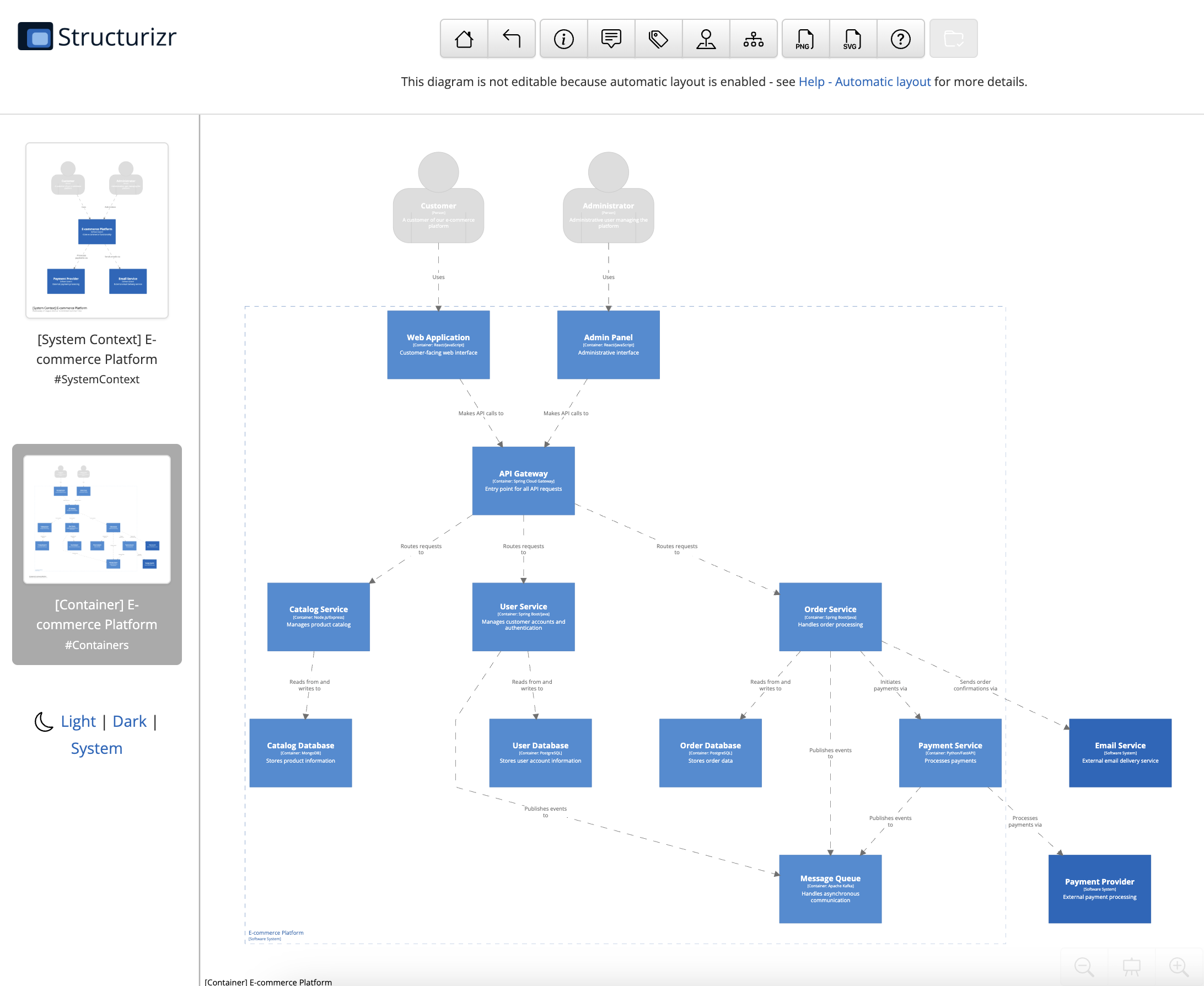
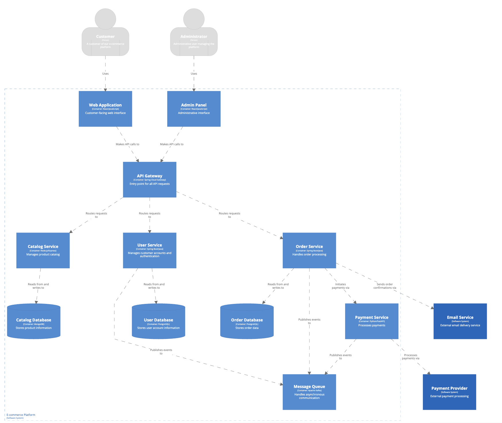
This DSL definition creates multiple views of our e-commerce system. The system context view shows how our platform interacts with users and external services. The container view reveals the internal microservices architecture, showing how services communicate through the API gateway and message queue.
Save your workspace.dl file and reload the Structurizer page in the browser to render the new diagram. You can navigate into the container diagram using either the diagram list view on the left side panel, or by clicking the zoom cursor on the software system.
Further Styling Options
The database containers in our diagram are currently rectangular boxes, the same as our other containers. A visual distinction would make them more easily identifiable by the viewer. We could change the shape of the databases to enable this.
Lets add a “Database” tag to the database container definitions that we can use in an element style.
userDatabase = container "User Database" "Stores user account information" "PostgreSQL" {
    tags "Database"
}
Then add a new style for the Database-tagged element with shape “cylinder”.
element "Database" {
    shape cylinder
}
Reload Structurizr Lite and our database containers are now rendered as cylinders rather than rectangles.
Modeling Component-Level Detail
For critical services, you can add component-level detail to show internal structure. Here’s how you might model the User Service components:
userService = container "User Service" "Manages customer accounts and authentication" "Spring Boot/Java" {
    authController = component "Authentication Controller" "Handles login and registration requests" "Spring MVC Controller"
    userController = component "User Controller" "Handles user profile operations" "Spring MVC Controller"
    authService = component "Authentication Service" "Implements authentication logic" "Spring Service"
    userService = component "User Service" "Implements user management logic" "Spring Service"
    userRepository = component "User Repository" "Data access for users" "Spring Data JPA"
    tokenService = component "Token Service" "Manages JWT tokens" "Spring Service"
}
This level of detail helps development teams understand the internal structure of services they’re working on while keeping the higher-level views clean and focused.
ADRs (Architecture Decision Records)
Architecture Decision Records (ADRs) are concise documents that capture important architectural decisions and their context. Structurizr supports managing ADRs alongside your architecture model, making it easy to keep decisions visible and version-controlled.
Adding ADRs in Structurizr DSL
You can add source-controlled ADRs in your architecture repository and use Structurizr to browse and read them.
Create a directory at docs/architecture-decision-records to hold your ADR markdown documents and add an example:
# Implement Event-Driven Architecture with Message Queues

Date: 2025-08-28

## Status

Accepted

## Context

Our microservices architecture requires reliable communication between services. We need to handle:

- Order processing workflows that span multiple services
- Real-time inventory updates across fulfillment and e-commerce systems
- Marketing campaign triggers based on customer behavior
- Asynchronous notifications and email sending
- Decoupling of services to prevent cascading failures

Synchronous API calls alone would create tight coupling and potential cascade failures.

## Decision

We will implement event-driven architecture using message queues for asynchronous communication:

- **Apache Kafka** for high-throughput event streaming (e-commerce and marketing systems)
- **AWS SQS** for reliable message delivery (fulfillment system)

Services will publish domain events (order placed, payment processed, inventory updated) and subscribe to relevant events from other services.

## Consequences

**Positive:**
- Loose coupling between services
- Better resilience - services can handle temporary unavailability of dependencies
- Scalability - async processing allows for better resource utilisation
- Audit trail - events provide natural business process logging
- Flexibility - new services can easily subscribe to existing events

**Negative:**
- Eventual consistency - data may be temporarily inconsistent across services
- Complexity in handling message ordering and duplicate processing
- Debugging distributed workflows becomes more challenging
- Need for sophisticated monitoring of message queues
- Potential message loss scenarios need handling

**Mitigation:**
- Implement idempotent message handlers
- Use message deduplication strategies
- Establish clear event schemas and versioning
- Implement comprehensive monitoring and alerting
- Design for graceful degradation when message queues are unavailable
Update your workspace to load the ADRs from the directory (you can also use the !adrs directive within a software system or a container element).
workspace "Retail Business" "Architecture for our online retail business" {
    !adrs docs/architecture-decision-records
}
Viewing ADRs in Structurizr Lite
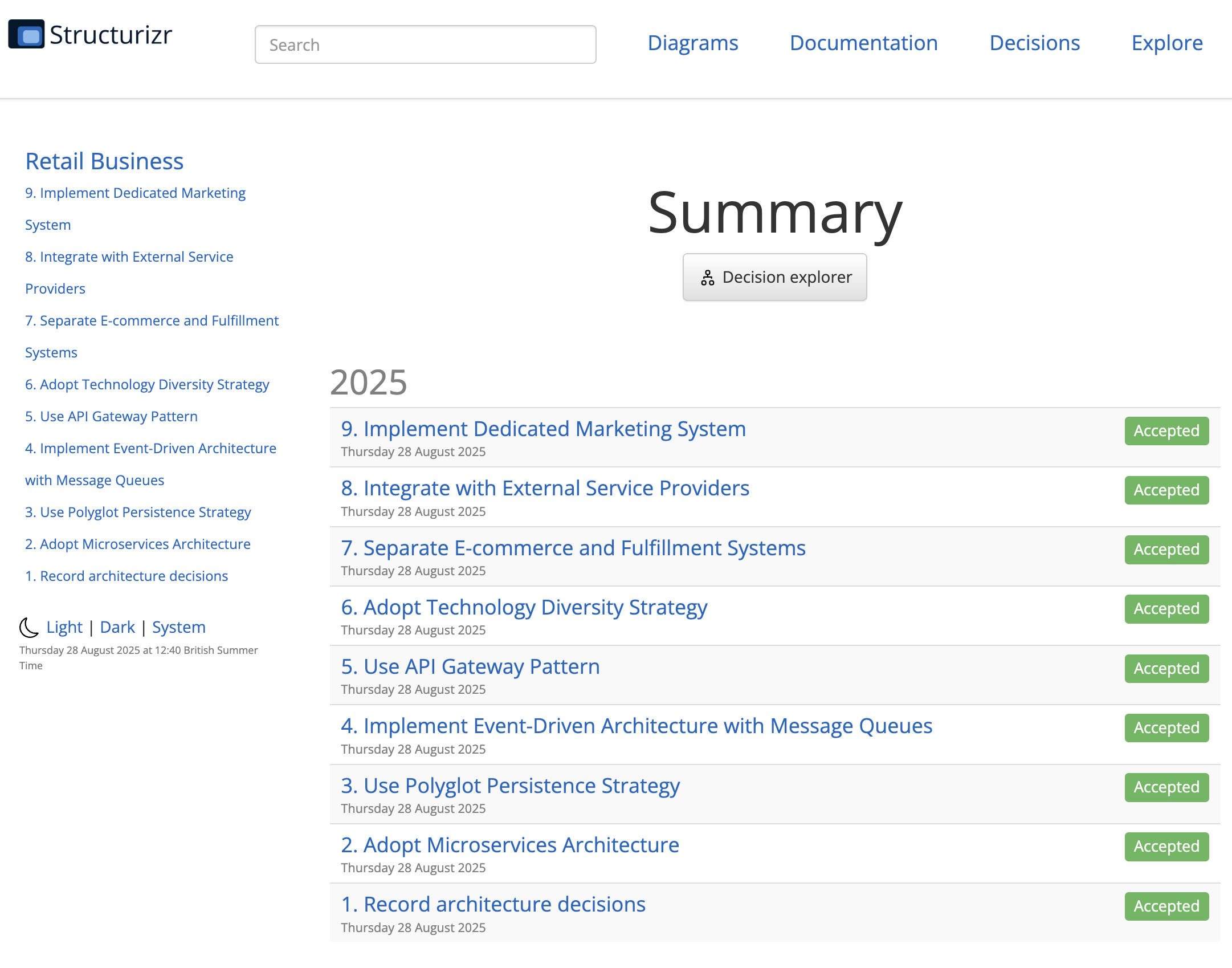
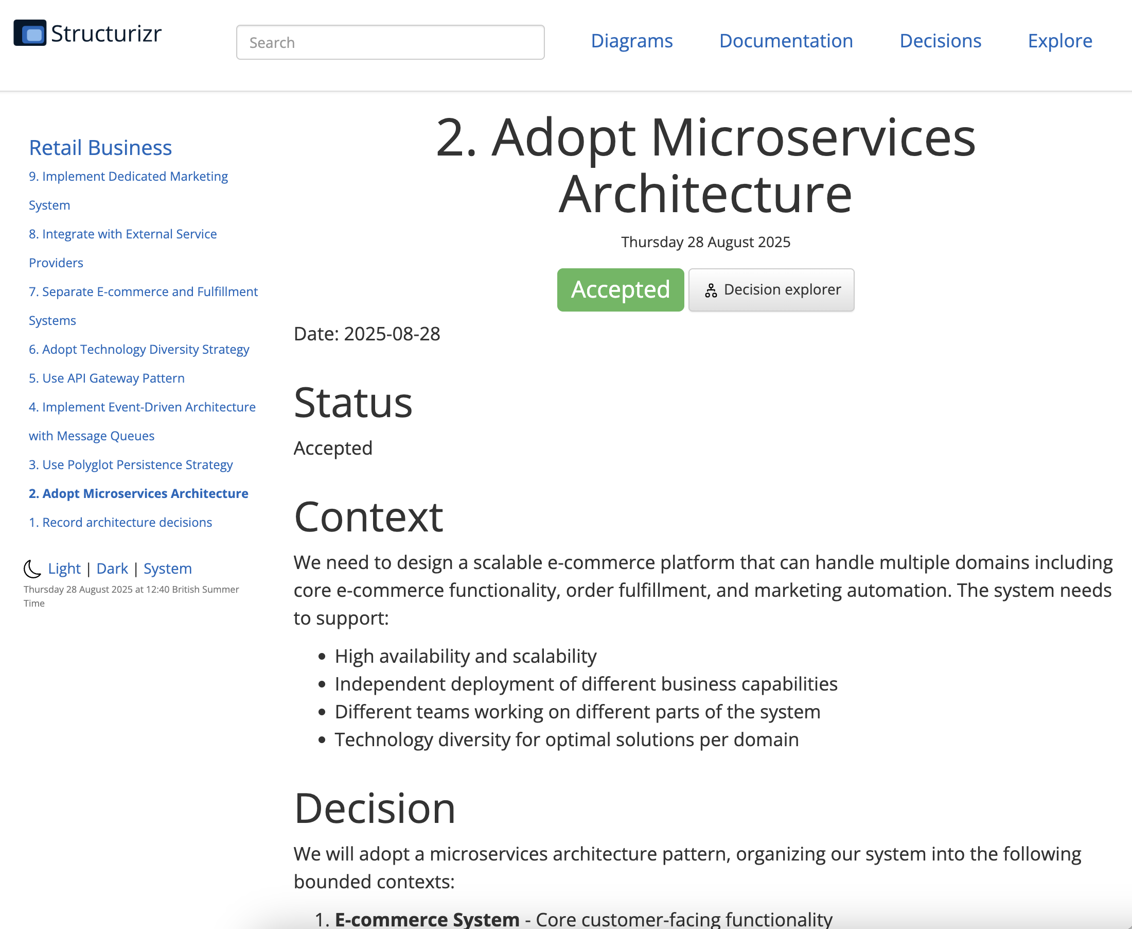
When you load your workspace in Structurizr Lite, ADRs appear in the documentation section. You can link decisions to specific elements (e.g. containers or systems) by referencing their IDs, providing context for why certain architectural choices were made.
Best Practices for Distributed Systems
When documenting distributed systems with C4 and Structurizr DSL, several practices will make your diagrams more valuable and maintainable.
Start with the system context and work your way down. Don’t try to model everything at once. Begin with a clear understanding of your system’s boundaries and external dependencies, then gradually add detail.
Group related containers using tags or groups. This helps when your system grows to dozens of services. You might tag all payment-related services or group services by business capability. The group keyword provides a way to define a named grouping of elements at the same level of abstraction, which will be rendered as a boundary around those elements.
Document key quality attributes in your descriptions. Don’t just say what a service does, mention if it’s high-availability, handles sensitive data, or has specific performance requirements.
Keep your DSL in version control alongside your code. This enables tracking changes over time and correlating architectural evolution with code changes.
Managing Complexity as Systems Grow
As your distributed system evolves, your C4 models will naturally grow more complex. Here are strategies for managing this complexity without losing clarity.
Create focused views for specific audiences or scenarios. You might create a deployment view showing how containers map to infrastructure, or a security view highlighting trust boundaries and data flows.
Use dynamic diagrams to show how your system behaves during key scenarios. Structurizr supports sequence diagrams that can illustrate the flow of requests through your distributed system during checkout, user registration, or other critical processes.
Establish governance practices around your architectural documentation. Assign ownership for keeping different parts of the model current, and include architecture reviews as part of your change management process.
Decentralising Architecture Diagrams
As distributed systems scale, it becomes impractical for a single team to maintain a monolithic DSL file describing the entire architecture. Structurizr DSL supports modularisation, allowing you to split your architecture model into multiple files. This enables different teams to own and update their respective parts of the system independently.
Using !include to Compose Models
You can break up your DSL into logical modules, such as per team, service, or bounded context, and use the !include directive to assemble them into a complete model. For example:
workspace "E-commerce Platform" "Architecture for our distributed e-commerce system" {
    !include teams/customer-team.dsl
    !include teams/order-team.dsl
    !include teams/payment-team.dsl

    views {
        !include views/system-context.dsl
        !include views/containers.dsl
        !include views/styles.dsl
    }
}
Each included file can define people, systems, containers, relationships, or views relevant to that domain. Teams can manage their own files in separate repositories or directories, enabling decentralised ownership and parallel development.
Using extends to Compose Models
Structurizr DSL provides a way to extend an existing workspace. This allows you to define your software systems and their relationships in a central file.
workspace "Retail Business" "Architecture for our online retail business" {
    !identifiers hierarchical

    model {
        # Define people and external systems
        customer = person "Customer" "A customer of our e-commerce platform"
        admin = person "Administrator" "Administrative user managing the platform"

        paymentProvider = softwareSystem "Payment Provider" "External payment processing"
        emailService = softwareSystem "Email Service" "External email delivery service"

        ecommerceSystem = softwareSystem "E-commerce Platform" "Core e-commerce functionality"
        fulfilmentSystem = softwareSystem "Fulfilment Platform" "Order fulfilment system"
        crmSystem = softwareSystem "CRM System" "Customer relationship management platform"
        analyticsSystem = softwareSystem "Analytics Platform" "Aggregates and analyzes business data"
        marketingSystem = softwareSystem "Marketing Automation" "Manages campaigns and customer engagement"
        inventorySystem = softwareSystem "Inventory Management" "Tracks stock levels and warehouse operations"
        supportSystem = softwareSystem "Customer Support" "Handles customer inquiries and support tickets"
        recommendationEngine = softwareSystem "Recommendation Engine" "Provides personalized product recommendations"
        searchService = softwareSystem "Search Service" "Enables product search functionality"
        shippingProvider = softwareSystem "Shipping Provider" "External shipping and logistics integration"
        taxService = softwareSystem "Tax Calculation Service" "Handles tax calculations and compliance"

        # Define relationships at the system level
        customer -> ecommerceSystem "Uses"
        admin -> ecommerceSystem "Administers"
        ecommerceSystem -> paymentProvider "Processes payments via"
        ecommerceSystem -> emailService "Sends emails via"
    }
}
Then you can extend the base workspace for each system using the extends keyword. The workspace being extended can be a local filename or a public HTTP URL.
workspace extends retail-business.dsl {
    model {
        !element ecommerceSystem {
            webApp = container "Web Application" "Customer-facing web interface" "React/JavaScript"
            adminPanel = container "Admin Panel" "Administrative interface" "React/JavaScript"
            apiGateway = container "API Gateway" "Entry point for all API requests" "Spring Cloud Gateway"

            userService = container "User Service" "Manages customer accounts and authentication" "Spring Boot/Java"
            catalogService = container "Catalog Service" "Manages product catalog" "Node.js/Express"
            orderService = container "Order Service" "Handles order processing" "Spring Boot/Java"
            paymentService = container "Payment Service" "Processes payments" "Python/FastAPI"

            userDatabase = container "User Database" "Stores user account information" "PostgreSQL" {
                tags "Database"
            }
            catalogDatabase = container "Catalog Database" "Stores product information" "MongoDB" {
                tags "Database"
            }
            orderDatabase = container "Order Database" "Stores order data" "PostgreSQL" {
                tags "Database"
            }

            messageQueue = container "Message Queue" "Handles asynchronous communication" "Apache Kafka"

            # Define relationships at the container level
            customer -> webApp "Uses"
            admin -> adminPanel "Uses"

            webApp -> apiGateway "Makes API calls to"
            adminPanel -> apiGateway "Makes API calls to"

            apiGateway -> userService "Routes requests to"
            apiGateway -> catalogService "Routes requests to"
            apiGateway -> orderService "Routes requests to"

            userService -> userDatabase "Reads from and writes to"
            catalogService -> catalogDatabase "Reads from and writes to"
            orderService -> orderDatabase "Reads from and writes to"
            orderService -> paymentService "Initiates payments via"

            paymentService -> paymentProvider "Processes payments via"
            paymentService -> messageQueue "Publishes events to"
            orderService -> messageQueue "Publishes events to"
            userService -> messageQueue "Publishes events to"

            orderService -> emailService "Sends order confirmations via"
        }
    }

    views {
        systemContext ecommerceSystem "SystemContext" {
            include *
            autoLayout
        }

        container ecommerceSystem "Containers" {
            include *
            autoLayout
        }

        styles {
            element "Person" {
                color #ffffff
                fontSize 22
                shape Person
            }
            element "Software System" {
                background #1168bd
                color #ffffff
            }
            element "Container" {
                background #438dd5
                color #ffffff
            }
            element "Database" {
                shape cylinder
            }
        }
    }
}
Decentralised Architecture Diagrams
The !includes and extends directives can be used to build a complete picture of your systems landscape, with decentralised architecture diagrams managed by different teams. See my GitHub repository Mapping-Distributed-Systems-with-C4-Diagrams-and-Structurizr-DSL for a complete example.
View a live demo of a static website with limited features at structurizr-sample.glen-thomas.com.
Best Practices for Modular DSL
- Define clear boundaries: Agree on naming conventions and IDs to avoid conflicts between modules.
- Centralise shared elements: Common definitions (e.g. external systems, global styles) can live in a shared file included by all modules.
- Automate integration: Use CI/CD pipelines to validate and assemble the full model from all parts, ensuring consistency and correctness.
Automating Documentation Generation
One of the biggest advantages of using Structurizr DSL is the ability to integrate architectural documentation into your development workflow. You can set up continuous integration pipelines that automatically regenerate diagrams when your DSL files change.
Consider creating a simple script that validates your DSL syntax and uploads diagrams to a shared location. This ensures your architectural documentation stays current without manual intervention.
You can also integrate with tools like PlantUML or export static images for inclusion in other documentation. The key is making architectural documentation a byproduct of your development process rather than a separate, easily-forgotten activity.
You could also use your DSL models to generate other artifacts; API documentation, service catalogs, or even infrastructure-as-code templates. This creates a single source of truth for your system’s structure that flows into multiple downstream uses.
Conclusion
The C4 model and Structurizr provide a powerful framework for documenting distributed systems that grows with your architecture. By treating architectural documentation as code, you can create maintainable, version-controlled representations of your system that integrate naturally with your development process.
The hierarchical nature of C4 diagrams ensures that different stakeholders get appropriate levels of detail, while Structurizr DSL’s textual approach makes it practical to keep documentation current in fast-moving distributed system environments.
Start simple with a system context diagram, add container-level detail for your key services, and gradually expand your model as your understanding and system complexity grow. Your future self, and your team, will thank you for the clarity and maintainability that this approach brings to distributed system architecture documentation.

Leave a comment